
Views: 0 Author: Site Editor Publish Time: 2026-09-15 Origin: Site


Poor extrusion design carries a heavy operational toll. Up to 80% of a component's manufacturing cost becomes permanently locked in during the initial engineering phase. Engineers constantly face a strict tension between structural requirements and manufacturability constraints. You need stiffness and load-bearing capacity, but the extrusion press demands geometries that prevent die wear, maintain extrusion speed, and avoid thermal distortion. Under extreme heat and pressure, aluminum behaves like a highly viscous fluid. Forcing this metal through complex steel dies requires a deep understanding of metal flow dynamics. This guide provides a technical framework for engineers and procurement teams to evaluate design viability. You will learn how to optimize profiles, specify the right hollow geometries, and select a manufacturing partner capable of executing your vision without unnecessary delays.
Uniformity Drives Yield: Maintaining consistent wall thickness across a profile prevents uneven cooling, warping, and premature die failure.
Hollows Increase Complexity: Specifying an aluminum extrusion tube or multi-void hollow requires specialized porthole or bridge dies, directly impacting tooling costs and production speed.
Alloy Selection Dictates Geometry: High-strength alloys (like 7000-series) have lower extrudability, restricting complex shapes and thin walls compared to standard 6000-series alloys.
Tolerances Must Align with Assembly: Over-specifying precision tolerances where standard commercial tolerances suffice unnecessarily inflates unit costs and lead times.
Every successful extrusion project begins with strict baseline evaluation criteria. You must define the load-bearing demands, environmental exposure limits, and weight constraints of the specific end-use application. These factors dictate the fundamental geometry of the part. Heavy structural loads often require thicker cross-sections and high-strength alloys. Corrosive environments demand specific surface treatments and alloys with high oxidation resistance. Weight-sensitive applications, such as aerospace or automotive framing, force engineers to push the limits of thin-wall extrusion.
To establish a functional baseline, engineering teams should evaluate the following parameters before sketching a profile:
Primary Load Vectors: Identify where bending, torsional, and compressive forces will intersect the profile.
Environmental Exposure: Determine if the part will face saltwater, extreme temperature fluctuations, or chemical washdowns.
Assembly Integration: Map out how this specific extrusion will mate with surrounding components, fasteners, or panels.
Weight Targets: Establish a maximum pounds-per-foot limit to guide wall thickness decisions.
The end-use application directly determines whether you should design a solid profile, a semi-hollow shape, or a fully hollow structure. Solid profiles are the easiest and most economical to extrude. Metal flows smoothly through a single-piece die. Semi-hollows introduce complexity by creating high tongue ratios that stress the die tooling. Fully hollow structures require two-piece dies to form internal voids. You must weigh the structural benefits of a hollow shape against the increased tooling complexity and slower production speeds.
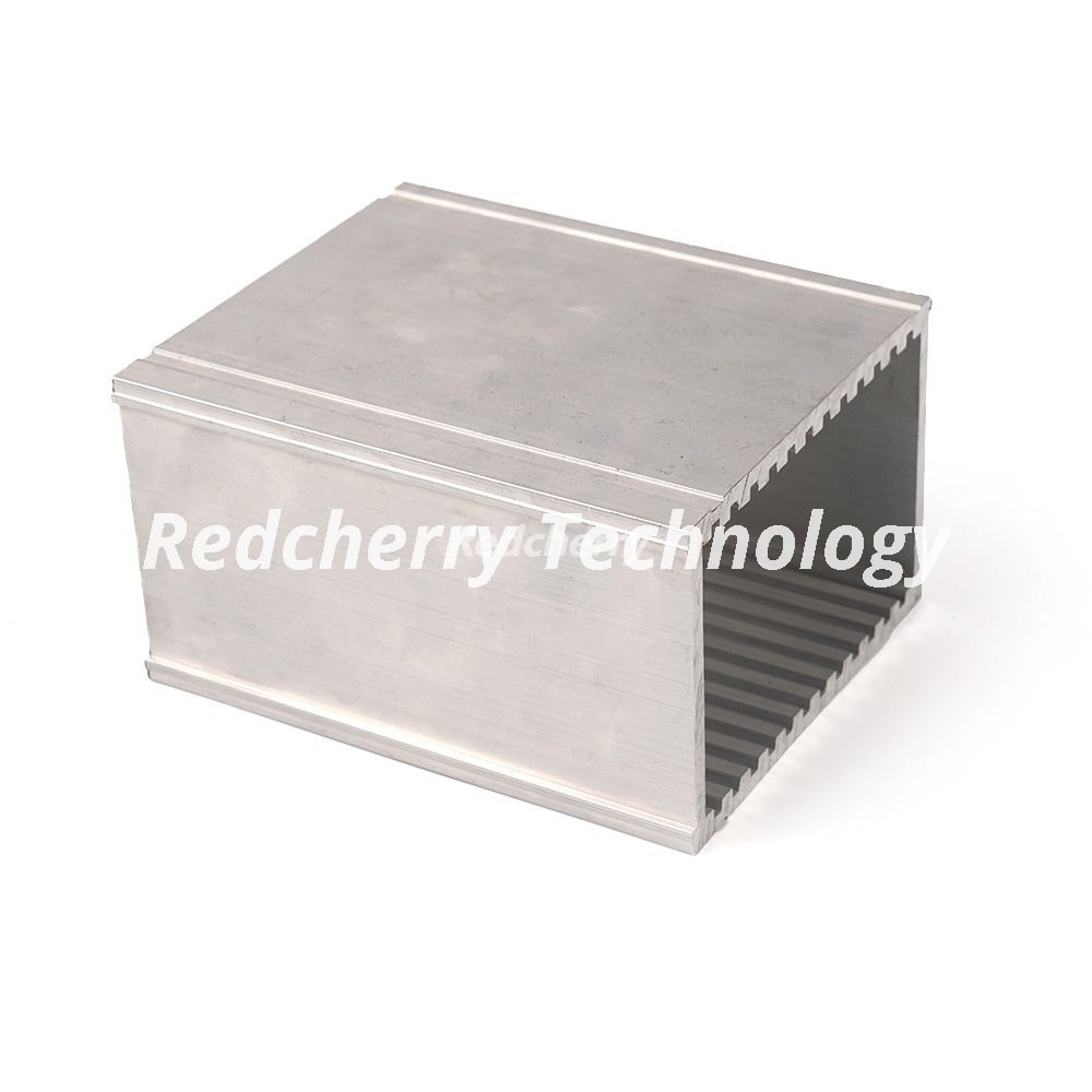
Hollow tubing offers exceptional structural advantages. A well-designed Aluminum Extrusion Tube provides an incredibly high strength-to-weight ratio. The closed-loop geometry inherently resists torsional forces better than open profiles like I-beams or C-channels. By pushing the mass of the material away from the neutral axis, hollow tubes maximize the moment of inertia without adding unnecessary weight.
Contrast this performance against solid bar stock. Solid bars offer massive compressive strength but suffer under bending and twisting loads relative to their weight. In structural framing and fluid transfer applications, solid stock is highly inefficient. Extruded tubes allow engineers to place metal exactly where the stress paths dictate. This targeted material distribution reduces overall assembly weight, lowers shipping costs, and improves the dynamic performance of the final product.
Profile Type | Torsional Rigidity | Tooling Complexity | Weight Efficiency | Best Application |
|---|---|---|---|---|
Solid Bar | Low | Low | Poor | Heavy compressive load bearing |
Open Channel (C, I) | Moderate | Low to Moderate | Good | Linear structural supports |
Hollow Tube | High | High | Excellent | Dynamic frames, fluid transfer |
Uniform wall thickness is the golden rule of aluminum extrusion. Metal flows through a die at different velocities based on the thickness of the opening. Thicker sections offer less resistance, causing the aluminum to flow faster. Thinner sections restrict flow. When a single profile contains drastically different wall thicknesses, the metal exits the die at uneven speeds. This unbalanced flow creates severe internal friction, leading to thermal distortion, bowing, and twisting.
When we set up a run-out table for a profile with a 0.250-inch wall intersecting a 0.050-inch wall, the results are highly predictable. The thick section retains heat and races ahead, while the thin section drags and cools rapidly. The entire length bows like a banana. Operators then have to stretch the metal aggressively to straighten it, which alters the final dimensions and introduces residual stress.
You must maintain consistent wall thickness wherever possible. If varying thicknesses are structurally necessary, keep the thickness ratio under 2:1. Never use sharp steps to change wall thickness. Instead, employ generous radii and gradual tapers. A smooth transition allows the metal flow to stabilize, reducing stress on the die and minimizing the risk of warping during the cooling phase.
Designing hollow profiles introduces significant tooling realities. Forming an Aluminum Extrusion Tube requires a porthole or bridge die. The metal splits apart to flow around an internal mandrel and then welds back together inside the die chamber before exiting. This process requires higher press tonnage and slows down production. Minimize unnecessary hollows to control your tooling costs and improve yield rates.
You must also consider the circumscribing circle size (CCS). The CCS is the smallest circle that can completely enclose the profile's cross-section. The overall dimension size of your tube dictates the required press size. Most commercial extruders operate presses that handle a CCS of 8 to 12 inches. Profiles exceeding this size require specialized heavy presses, drastically reducing your vendor options and increasing costs.
Evaluate the trade-offs between seamless and structural porthole-extruded tubes. Seamless tubes are extruded over a piercing mandrel from a hollow billet. They contain no weld seams, making them mandatory for high-pressure fluid applications. Porthole-extruded tubes feature longitudinal weld seams. While perfectly adequate for most structural framing, these seams can fail under extreme internal hydrostatic pressure.
Sharp corners are the enemy of extrudability. Both internal and external sharp corners create massive stress concentrations within the steel die. As the pressurized aluminum forces its way through the opening, these stress points fatigue the tooling, leading to premature die breakage. Sharp corners also disrupt the smooth flow of metal, causing surface tearing and dimensional instability.
Standard engineering practice dictates adding radii to all corners. A minimum corner radius of 0.015 to 0.031 inches significantly improves extrudability. Larger radii allow the metal to flow smoothly, extending die life and yielding a superior surface finish. Always round off non-critical corners to optimize the manufacturing process. When transitioning between a thick web and a thin flange, use a taper that spans at least three times the difference in thickness.
Symmetrical designs naturally balance metal flow. When the left and right halves of a profile mirror each other, the aluminum exits the die at a uniform velocity. Symmetrical shapes also cool at consistent rates on the run-out table. This uniform cooling prevents the profile from bowing or twisting as it solidifies.
Asymmetrical designs force the metal to flow unevenly. The heavier side retains heat longer, shrinking more during the cooling process and pulling the profile out of straightness. If an asymmetrical design is unavoidable, you must implement mitigation strategies. Add non-functional ribs or grooves to the lighter side to balance the cross-sectional mass. This artificial balancing stabilizes the thermal dynamics and keeps the extrusion straight.
The placement of internal features requires careful calculation. Screw bosses, mounting webs, and snap-fit channels must be positioned relative to the outer walls to ensure proper metal flow. Placing heavy details too close to the edge of a thin wall starves the thinner section of material, causing incomplete fills and surface defects.
Avoid creating deep, narrow channels. These geometries create high tongue ratios in the die. The tongue is the piece of steel that forms the channel. If the channel is too deep and narrow, the steel tongue becomes fragile. The immense pressure of the flowing aluminum will snap a weak die tongue, destroying the tool. A standard rule of thumb is to keep the depth-to-width ratio of any channel below 3:1. Redesign these features by widening the channel or reducing its depth to maintain a safe tongue ratio.
Extrudability measures how easily an alloy flows through a die and achieves complex shapes. This metric inversely correlates with mechanical strength. Highly extrudable alloys allow for intricate details, thin walls, and fast production speeds. High-strength alloys resist deformation, requiring massive press pressure and forcing slower extrusion rates.
Alloy 6063 represents the industry standard for extrudability. It flows beautifully, handles complex architectural shapes, and accepts anodizing exceptionally well. However, its yield strength is relatively low. Alloy 6061 offers much higher mechanical strength, making it the default choice for structural applications. The trade-off is lower extrudability. You cannot design the same thin-walled, intricate features in 6061 that you can in 6063 without risking die failure.
Alloy Grade | Extrudability Rating | Relative Strength | Primary Use Case |
|---|---|---|---|
6063 | Excellent | Low to Moderate | Architectural trim, heat sinks, complex hollows |
6005A | Good | Moderate | Transit vehicles, structural platforms |
6061 | Fair | High | Heavy structural frames, machine bases |
7075 | Poor | Very High | Aerospace components, high-stress military gear |
Post-extrusion thermal treatments dictate the final mechanical properties of the profile. Tempering designations like T4, T5, and T6 indicate specific cooling and artificial aging processes. T5 tempering involves cooling the metal directly from the extrusion press and artificially aging it in an oven. T6 requires a separate solution heat treatment, rapid quenching, and artificial aging to achieve maximum yield strength.
Quenching introduces severe risks for complex or thin-walled profiles. Rapidly cooling the hot metal in water locks in the grain structure but causes violent thermal contraction. Thin walls and asymmetrical shapes will warp heavily during a water quench. We frequently see parts twist beyond repair if the geometry cannot handle the thermal shock. Engineers must account for this distortion risk when specifying T6 tempers on delicate geometries, often requiring custom quenching fixtures just to hold the part straight.
Every dimension on an extrusion carries a tolerance. Industry standards, such as those published by the Aluminum Association, define acceptable variations in cross-sectional dimensions, straightness, twist, and angularity. These standard commercial tolerances are achievable with standard tooling and normal production speeds.
Demanding tighter-than-standard tolerances severely inflates unit costs. Precision tolerances require constant die corrections, slower press speeds, and higher scrap rates. Only specify precision tolerances on critical mating surfaces. Allow standard tolerances on all non-functional dimensions to keep production costs manageable and lead times short.
Extrusion allows you to build assembly features directly into the profile. You can design snap-fits, screw bosses, sliding tracks, and hinge joints right into the cross-section. This eliminates the need for secondary machining and separate fasteners, drastically reducing final assembly time.
However, treating aluminum like steel is a fundamental flaw. Aluminum lacks the stiffness of steel. You cannot rely on simple butt joints or standard welding techniques without compromising structural integrity. Aluminum requires specific joint geometries to maximize stiffness. Utilize interlocking profiles that distribute loads across a larger surface area.
Integrate 3-way corner brackets and internal connectors to optimize the strength of your framework. An Aluminum Extrusion Tube relies on rigid corner connections to maintain torsional stability. Internal connectors hidden inside the hollow voids provide massive pull-out strength without disrupting the clean exterior aesthetics of the frame. When designing screw bosses, ensure the gap is sized correctly for the specific thread-forming screw you intend to use, allowing the metal to displace without splitting the boss.
Tooling costs scale directly with profile complexity. Solid dies are relatively inexpensive. They consist of a single steel plate and require minimal machining. Hollow dies are highly complex. A bridge or porthole die requires multiple interlocking steel components to suspend the internal mandrel. This complexity doubles or triples the initial tooling investment.
Pushing the limits of profile complexity also guarantees expensive die trials. Complex shapes rarely extrude perfectly on the first attempt. The die must be tested, pulled from the press, and manually corrected by a toolmaker. Multiple revisions consume press time and delay production. Designing within standard extrudability guidelines minimizes the need for extensive die trials.
Profile design directly impacts surface quality. Thick internal webs located directly behind exposed cosmetic surfaces cause "sink marks." As the thick web cools and shrinks, it pulls the thinner cosmetic face inward, creating a visible depression or cooling streak. You must manage the mass ratio between internal webs and external faces to prevent these defects. Keep internal webs to 50% or less of the thickness of the adjoining exterior wall.
You can mask cosmetic defects using intentional decoration strategies. Large, perfectly flat surfaces highlight every minor extrusion line or handling scratch. Incorporate shallow grooves, serrations, or textured patterns into flat faces. These features break up the visual plane and naturally hide die lines, improving the perceived quality of the part.
Design also impacts secondary operations. Deep, narrow channels are difficult to powder coat because of the Faraday cage effect, which repels the charged powder particles. Complex internal geometries complicate CNC machining by restricting tool access. Always evaluate how your extrusion design will interact with downstream finishing and machining processes.
Successful aluminum extrusion design requires a continuous compromise between structural ideals and the physical realities of metal flow and die tooling. You cannot force complex, unbalanced geometries through a press without paying a premium in tooling costs, scrap rates, and delayed lead times. Procurement and engineering teams must engage extrusion manufacturers early in the design phase. Validate your die viability, confirm your alloy selection, and ensure your dimension sizing fits within standard press capabilities before locking in the final drawings.
Initiate a Design for Manufacturing (DFM) review with a qualified vendor immediately.
Order a 3D printed cross-section of your profile to physically verify assembly fit and joint clearances.
Audit your tolerance specifications and remove precision requirements from all non-mating surfaces.
Redesign any sharp corners or unbalanced wall thicknesses to improve extrudability and lower tooling costs.
A: Minimum wall thickness depends on the specific alloy and the overall profile size. For highly extrudable alloys like 6063, walls can generally range from 0.040 to 0.060 inches. Higher-strength structural alloys like 6061 require thicker walls, typically starting around 0.062 inches, to prevent die breakage and ensure proper metal flow.
A: Solid extrusions use a simple, single-piece die. Hollow extrusions require a complex two-piece die system, usually a porthole or bridge die. This setup uses a suspended mandrel to form the internal void and a cap to form the outside shape. This complexity significantly increases tooling costs and maintenance.
A: Extrusion size is limited by the Circumscribing Circle Size (CCS). Common commercial presses easily handle a CCS of 8 to 12 inches. While specialized heavy presses can extrude profiles up to 20 inches or more, vendor availability for these massive sizes drops significantly, and costs rise exponentially.
A: Varying wall thicknesses cause the aluminum to flow at different speeds through the die and cool at different rates on the run-out table. This uneven thermal dynamic causes the metal to warp, bow, or twist. Uniform thickness ensures stable metal flow and dimensional accuracy.
A: While technically possible, sharp corners create severe stress concentrations that cause premature die wear and breakage. They also disrupt smooth metal flow, leading to surface tearing. A minimum radius of 0.015 inches is standard engineering practice to ensure tooling longevity and part quality.
A: Alloy 6061-T6 is the industry standard for structural aluminum extrusion tubes. It provides an excellent balance of high yield strength, good weldability, and moderate extrudability, making it ideal for load-bearing frames and heavy-duty applications.
A: Large, flat surfaces easily show die lines, scratches, and sink marks. To hide these defects, incorporate decorative grooves, ribs, or textured patterns into the profile design. These intentional features break up the flat visual plane and naturally mask minor cosmetic imperfections.


